
Final Project

My final project which I named REFLAX is a kinetic interctive mirror that interacts with anyone who passes infornt of it by flapping its front golden plates. The project simply consists of DC motors that's connected to the plates by a mechanism that I designed and printed, and every motor or lets call it module has its own microcontroller and motor driver, then all of them are connected to one master board that drives the whole project.
Before building the project and taking serious steps in it I needed to make a low-fidelity prototype of the mechanism I wanted to build. So I got some old cardboard boxes and started cutting the plates and got a DC motor we had at Fab Lab Egypt and made the mechanism out of them as shown.
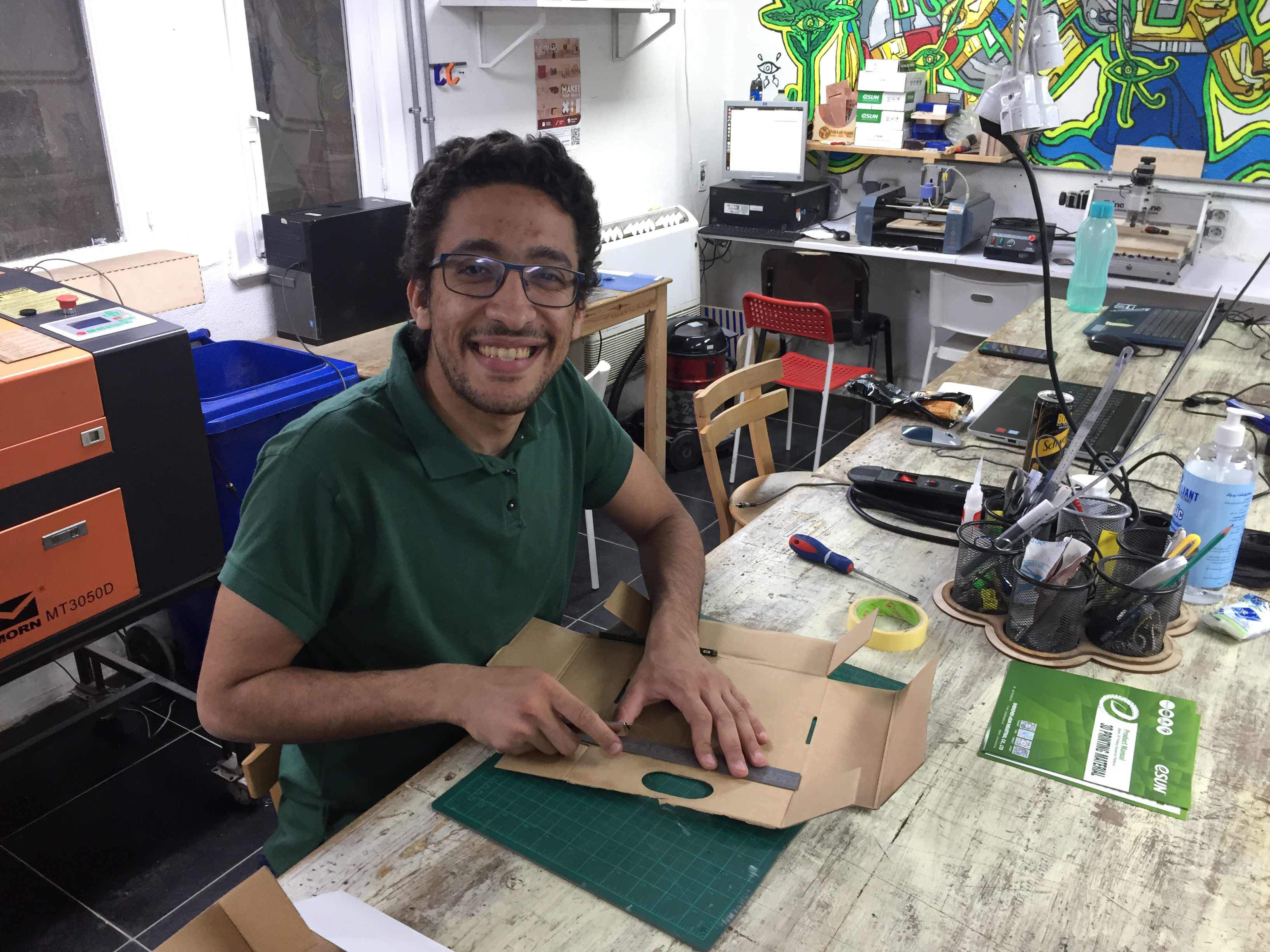
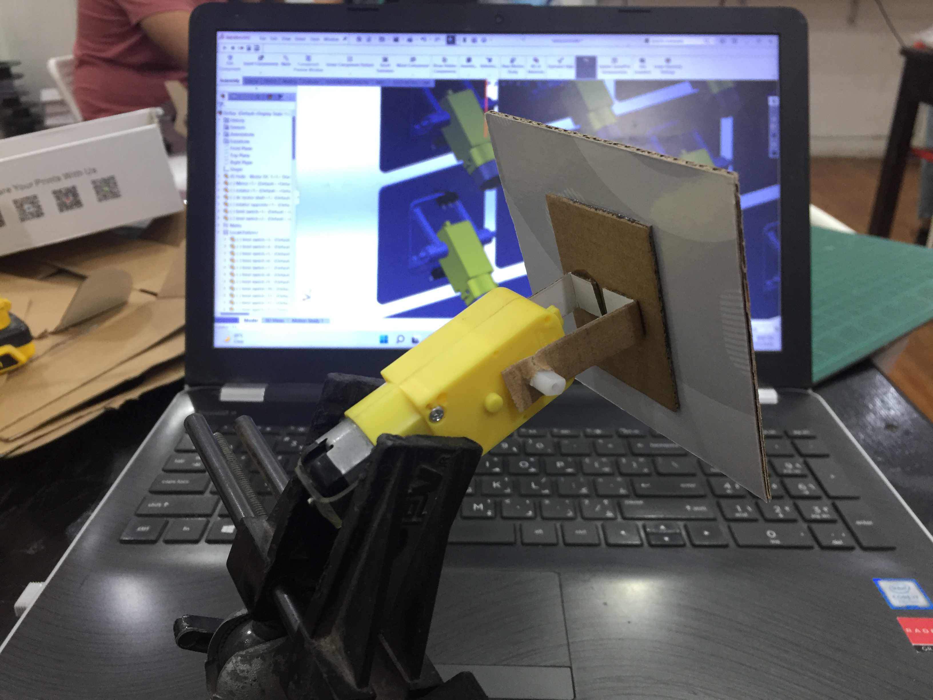
Then I started testing the motion of the mechanism and the possibilities of adding limit switches to stop the plate on the way up and down.
Moving mechanism
After that I started designing the CAD of the whole project and I had to design:
- The Moving mechanism connected to the DC motor
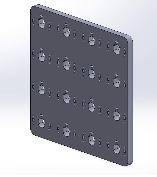
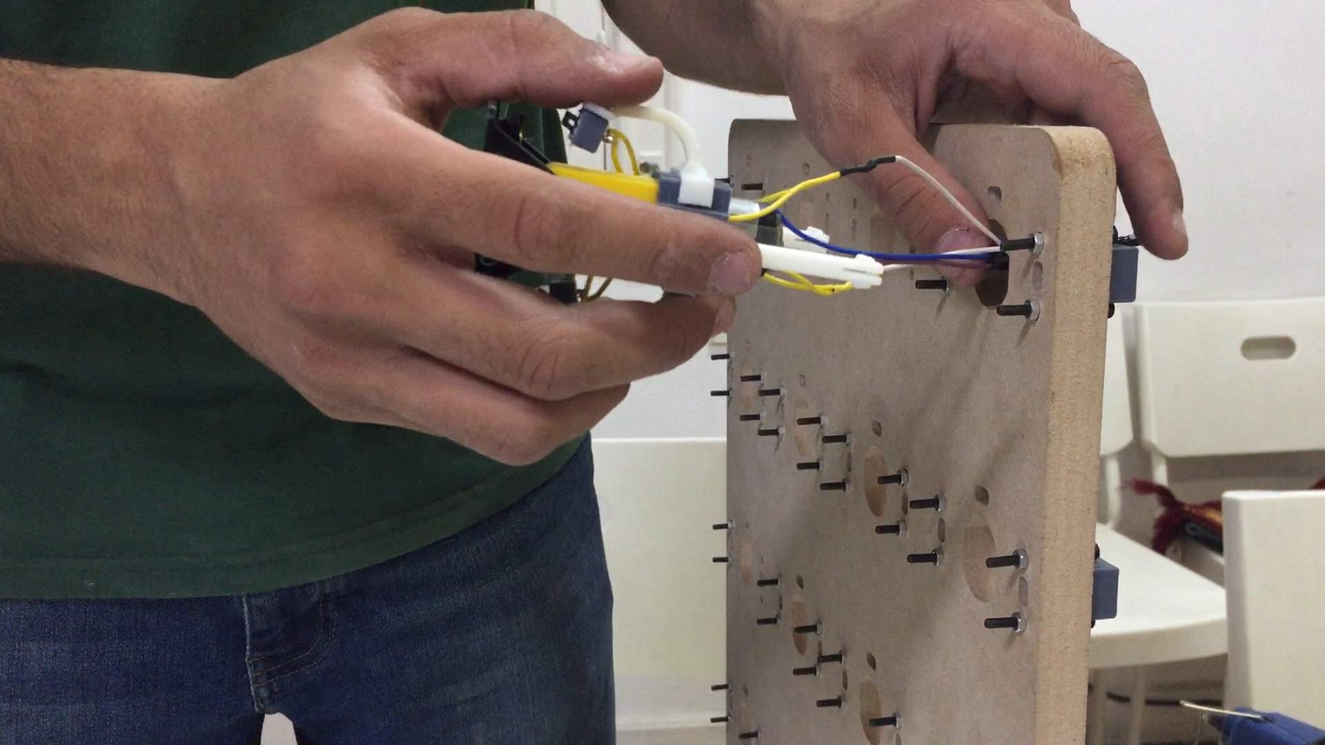
- The board that will hold the modules together
- The back box that will hold the electronic boards
Computer-Aided Design
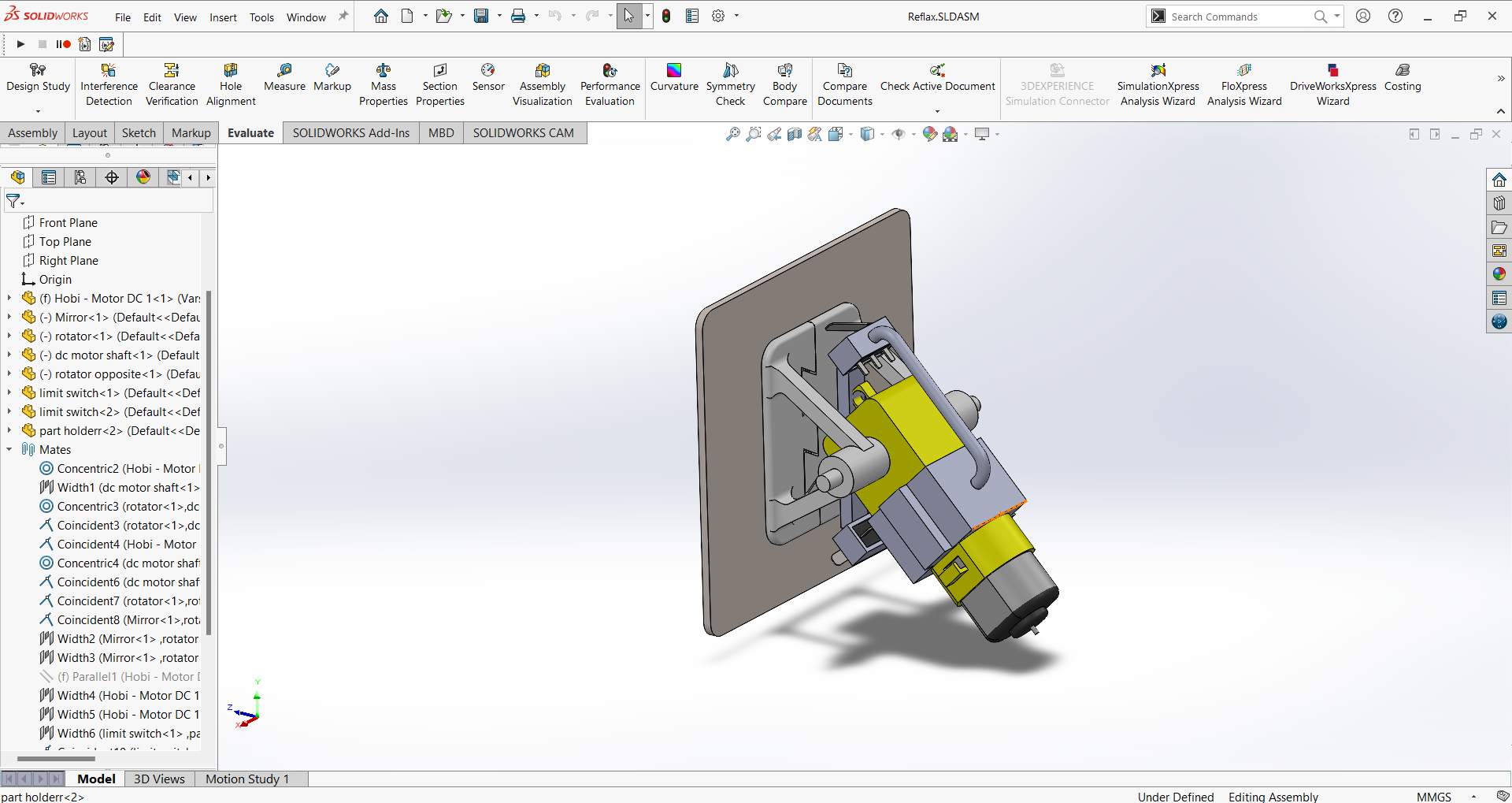
First I started by designing the DC motor and the parts that will be connected to it and attached to the front plate. All parts will be designed according to the 3D printing design rules which makes 3D printing easier and reduce the amount of supports as much as possible.
Each module has 7 3D printed parts and I added 2 limit switches in order to stop the plate from going further than a certain distance I measured.
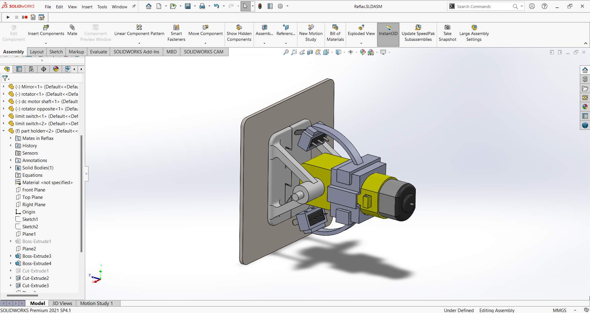
Click on the button below to view the 3D model of the project.
And I also made a rendered image of the project on SolidWorks.
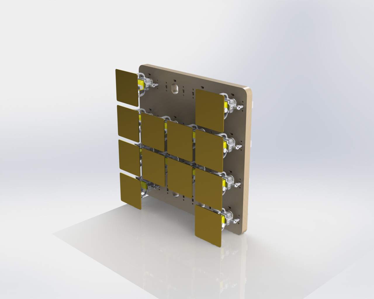
Moving mechanism
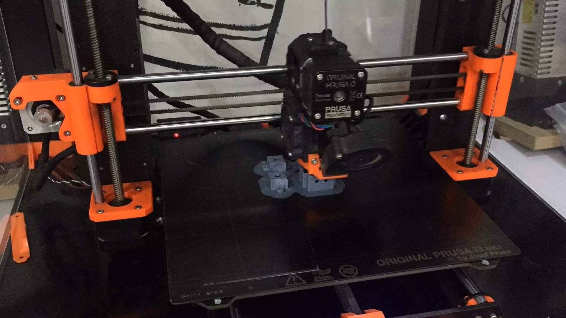
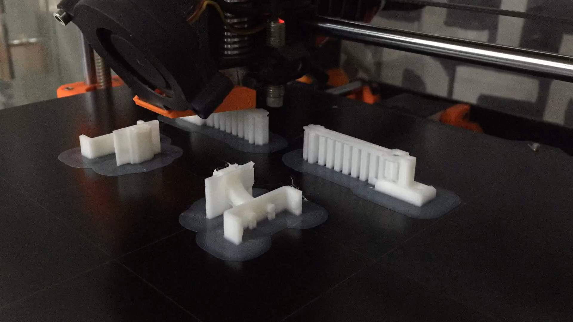
3D Printing
I had to 3D print all the parts I designed, and that's what I did using Prusa MK3S printer and printing by by PLA filament with the following printing settings using CURA slicer:
- Layer height 0.2mm
- Infill 20%
- Shells 2
- Support Enabled
- Nozzle temperature 215 C°
- Bed temperature 60 C°
Now each module consists of 7 3D printed parts as shown below, all I need now is to start assembling them.
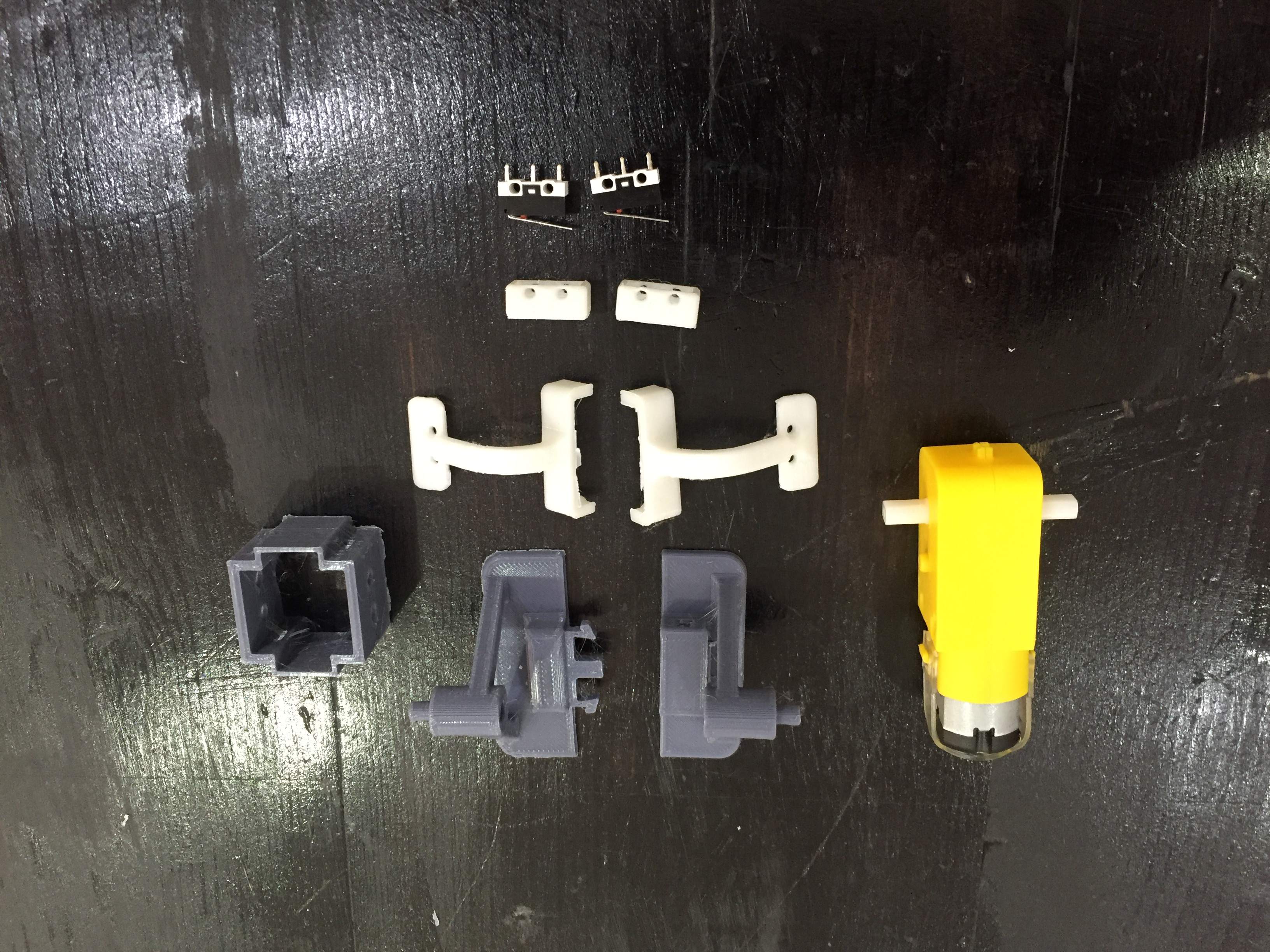
1 Module parts
Assembling the modules
Electronics Design
In this section I wanted to make 3 types of boards. First is the master board containing the Attiny1614 microcontroller and the power socket supplying 5V to all the microcontrollers following (Slaves). The second type is the first slave which will be controlled also by the master board but will have its own power source for the DC motor drivers which supplies the motors with the power, and taking its own power for the MCU from the master board. Finally the following slaves which will not have any additional power sources as thay will take the MCU power from the master and the DC motor drivers' power from the first slave.
The whole connection is demonstrated in th efollowing picture as I had to draw that on a whiteboard in order to brainstorm every connection where should it be.
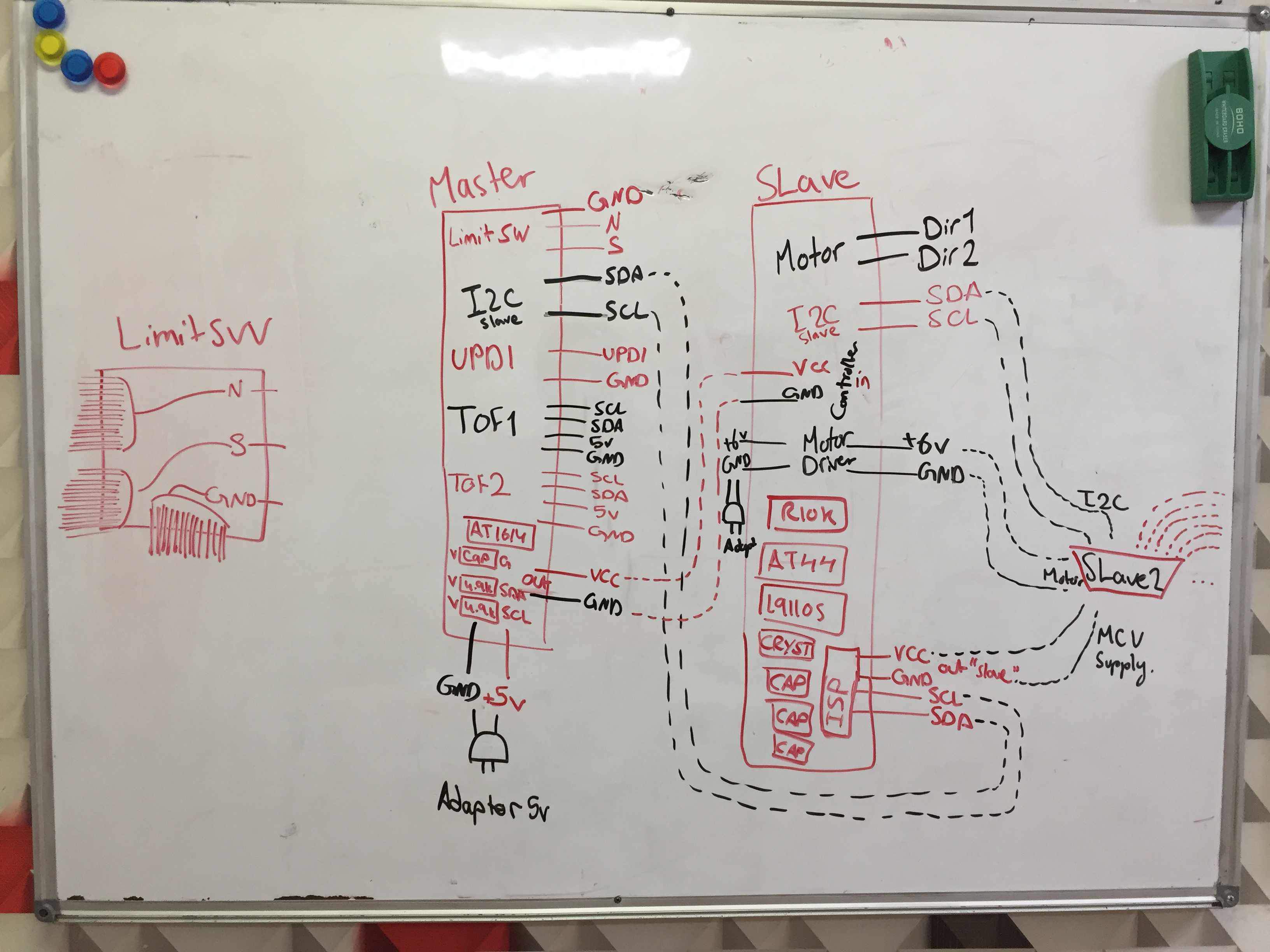
Whole connection
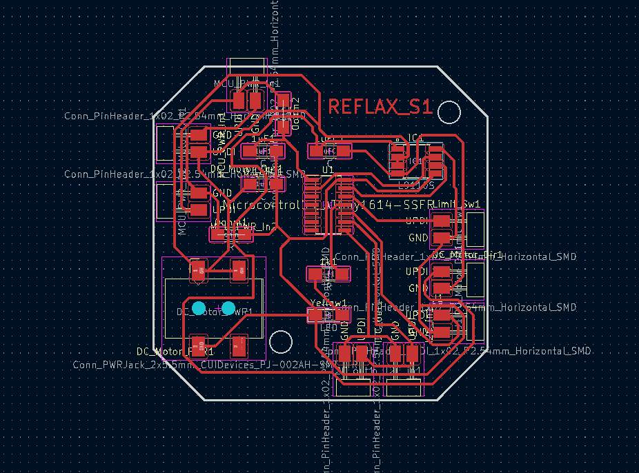
Which I then had to draw on KiCAD to be able to copy each board alone without getting anything wrong and to make it infront of me the whole time.
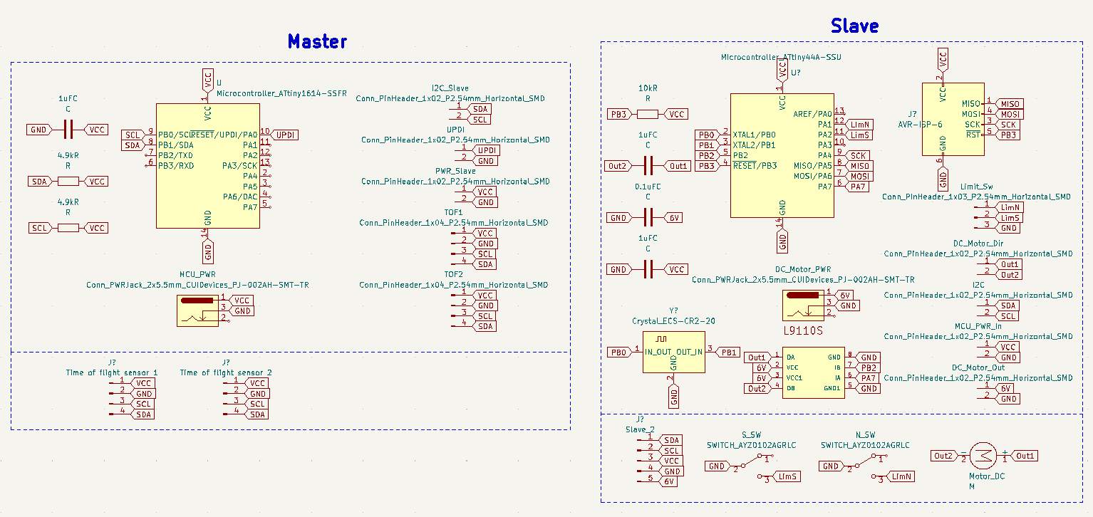
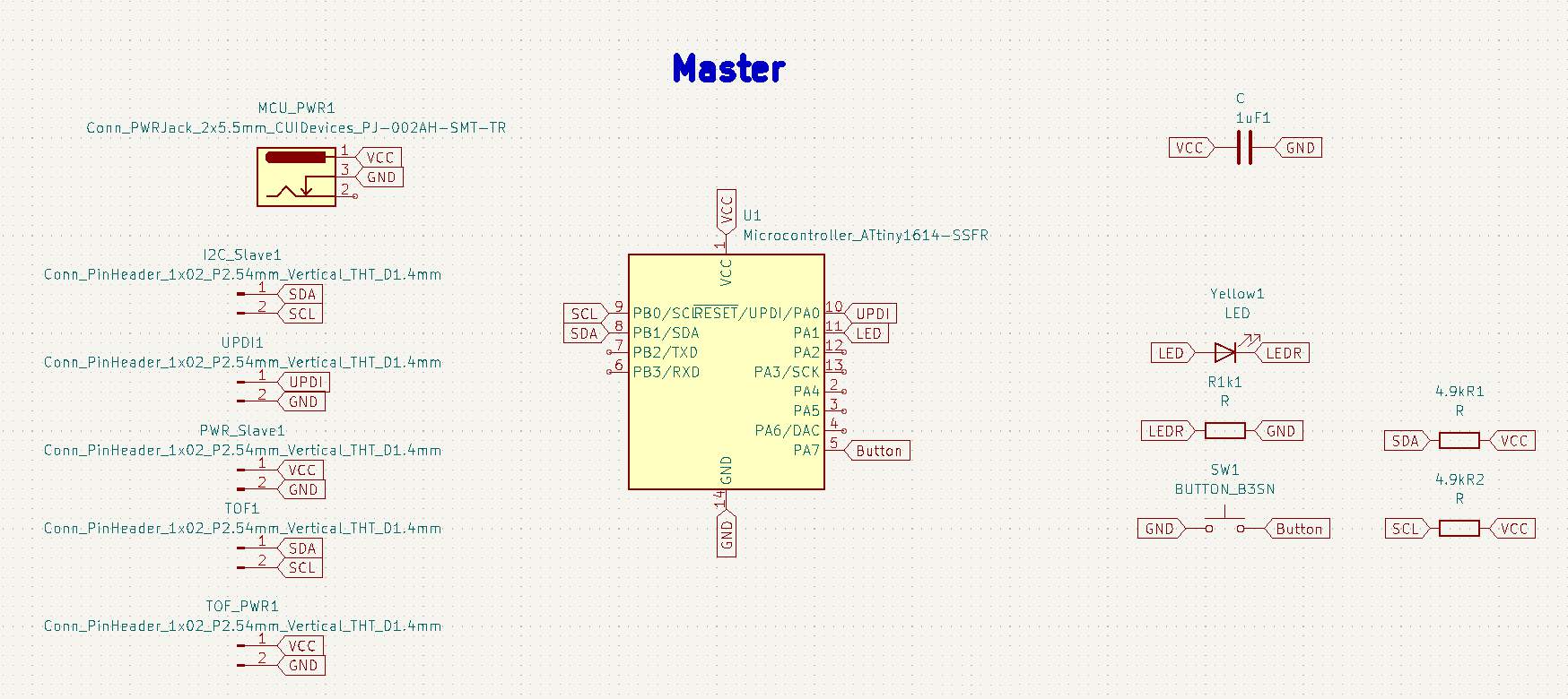
After that I separated every board as explained earlier into its own schematic and board, so for the Master board we had the following components:
- Attiny1614 (x1)
- Connector power jack (x1)
- 1uF capacitor (x1)
- 1k ohm resistor (x1)
- LED (x1)
- 4.9k ohm resistor (x1)
- Push button (x1)
- Male pin headers x2 (x5)
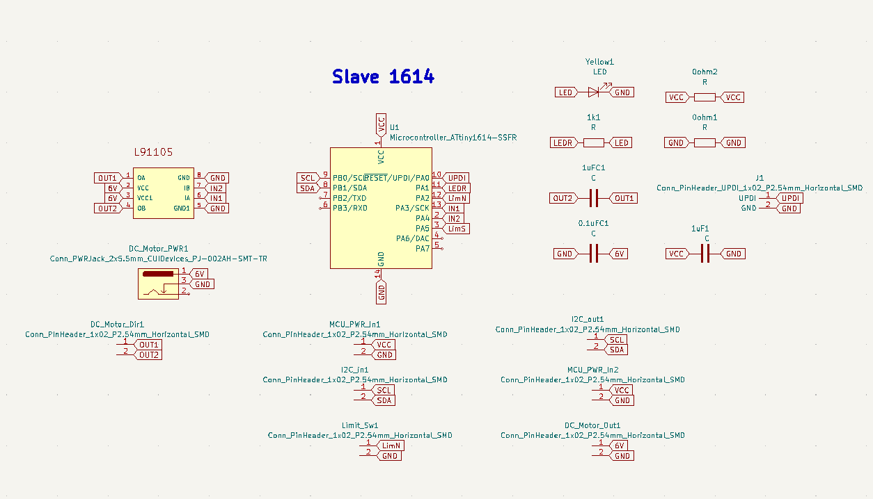
For the first slave I had to put the power connector as mentioned earlier for the motors' power and it had the following components:
- Attiny1614 (x1)
- Connector power jack (x1)
- 1uF capacitor (x2)
- 0.1uF capacitor (x1)
- 0 ohm resistor (x2)
- 1k ohm resistor (x1)
- LED (x1)
- Male pin headers x2 (x8)
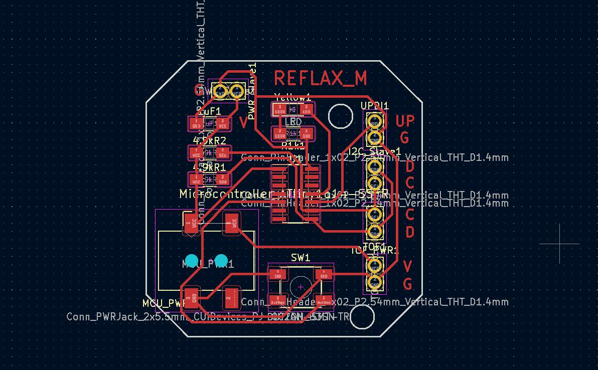
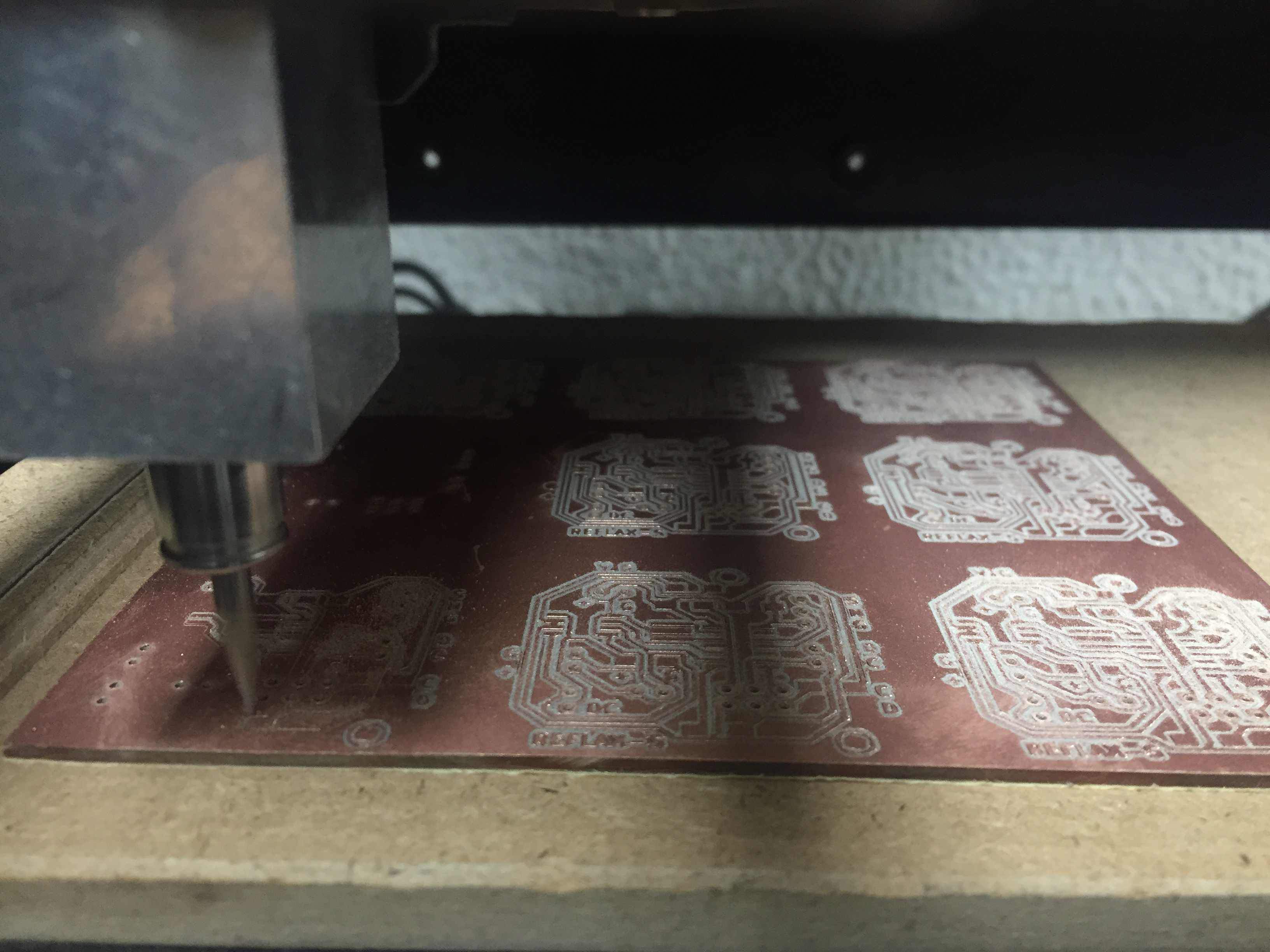
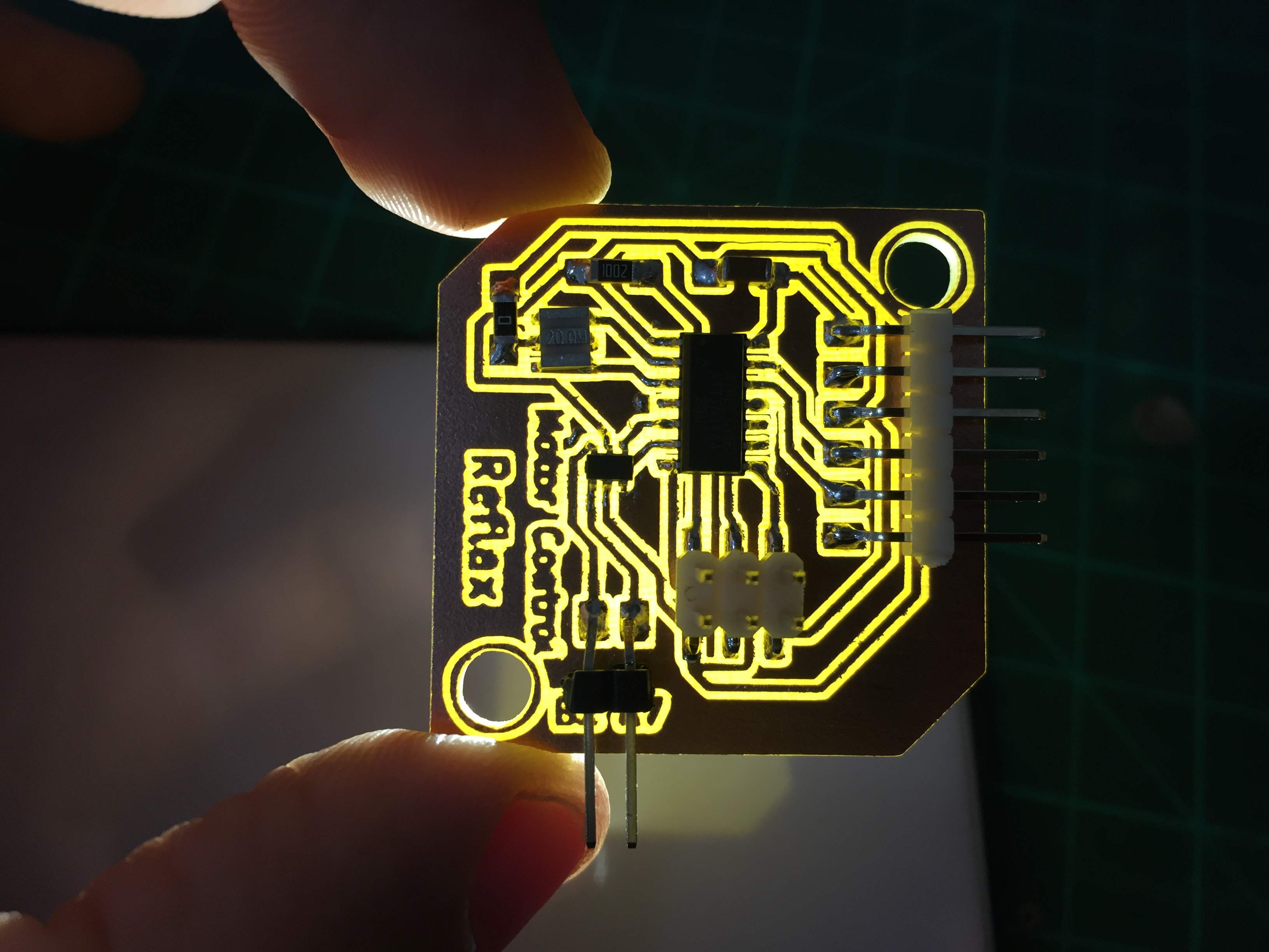
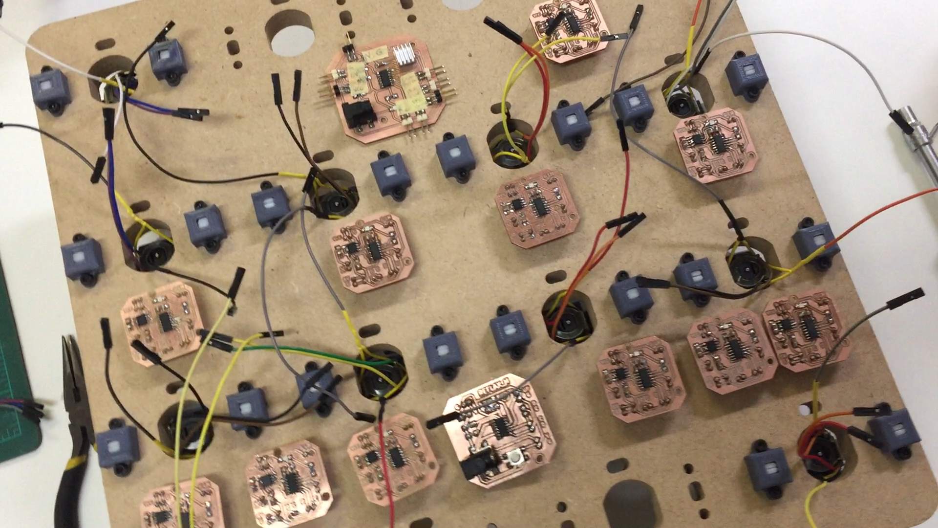
The I started fabricating the board on the Rolland MDX-20 milling machine we have at Fab Lab Egypt. I started by the Master board and soldered the components according to the layout.
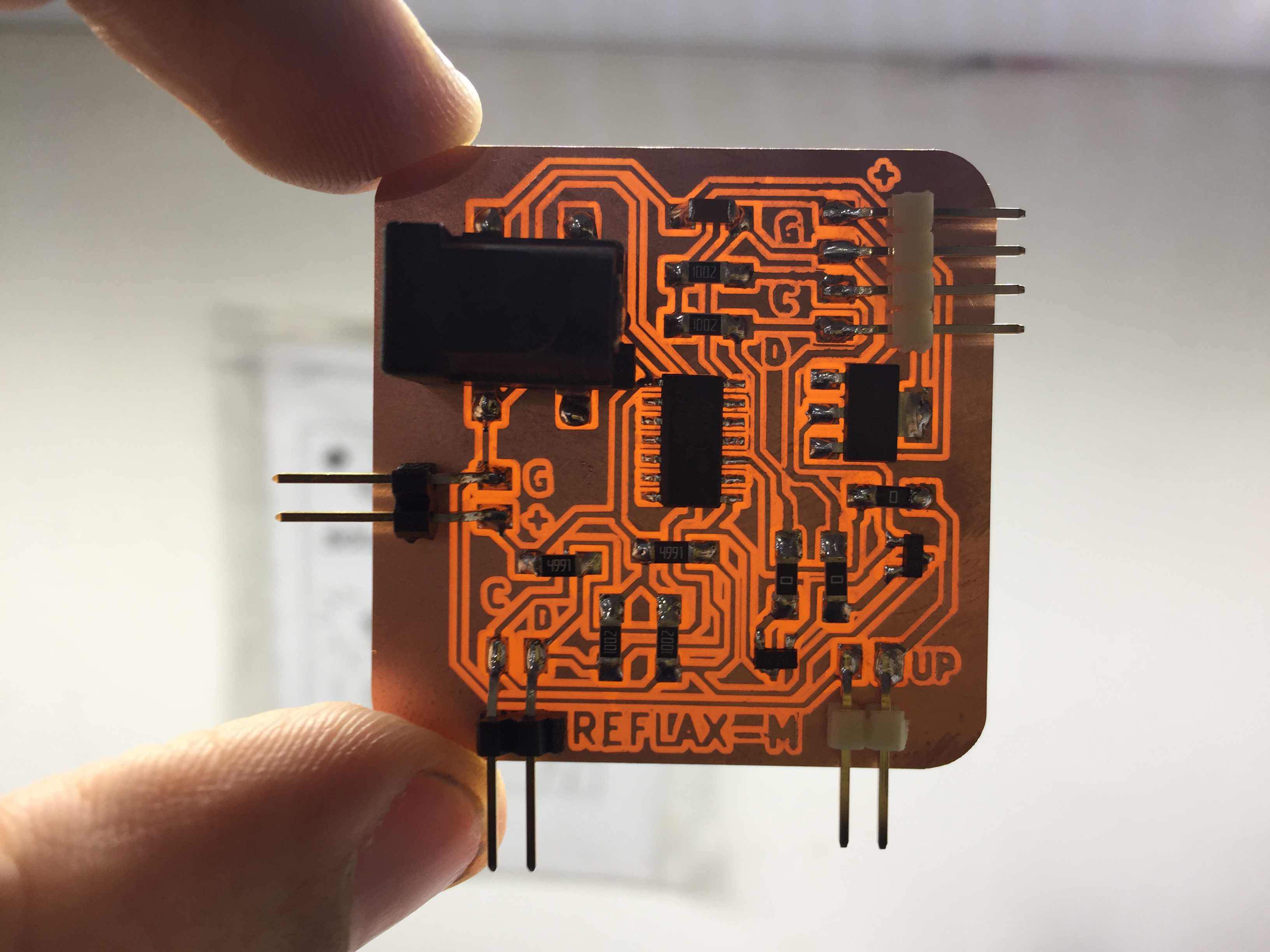
But for the slaves I needed to make a full 9*9 panel twice to make all the boards needed.
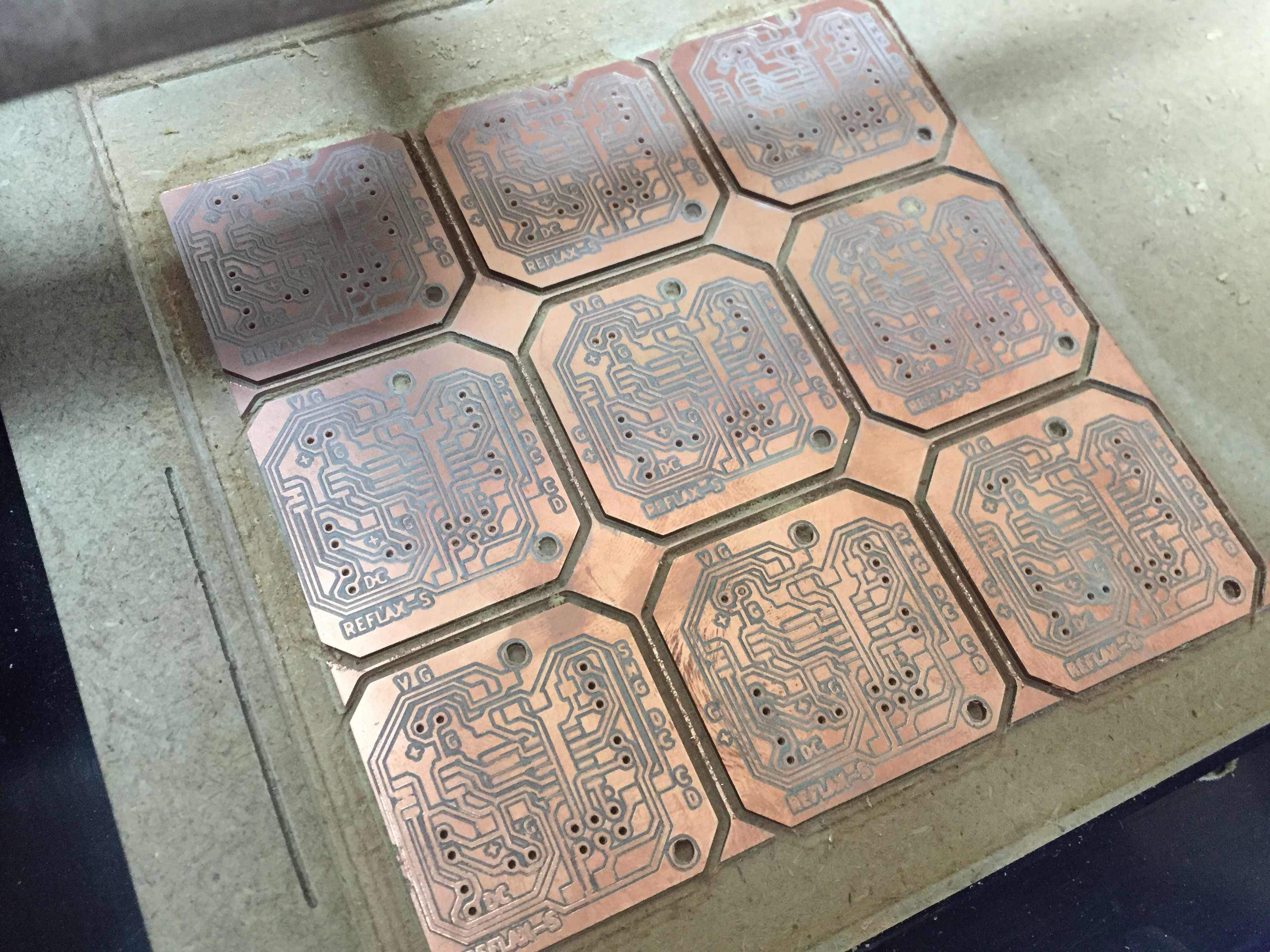
Then I soldered all the boards as shown below which took around 4 hours of just soldering.
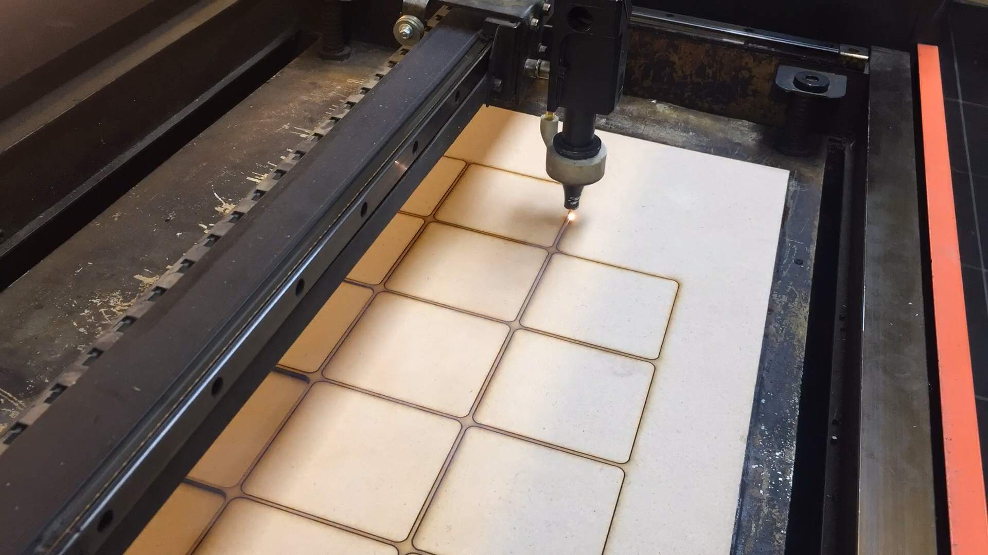
Computer-Controlled cutting
Here is the time for cutting the plates which will be attached in front and that will be flapping. I made a 8*8 cm^2 square with a 5mm fillet at all corners, and I cut them on 3mm thick MDF wood.
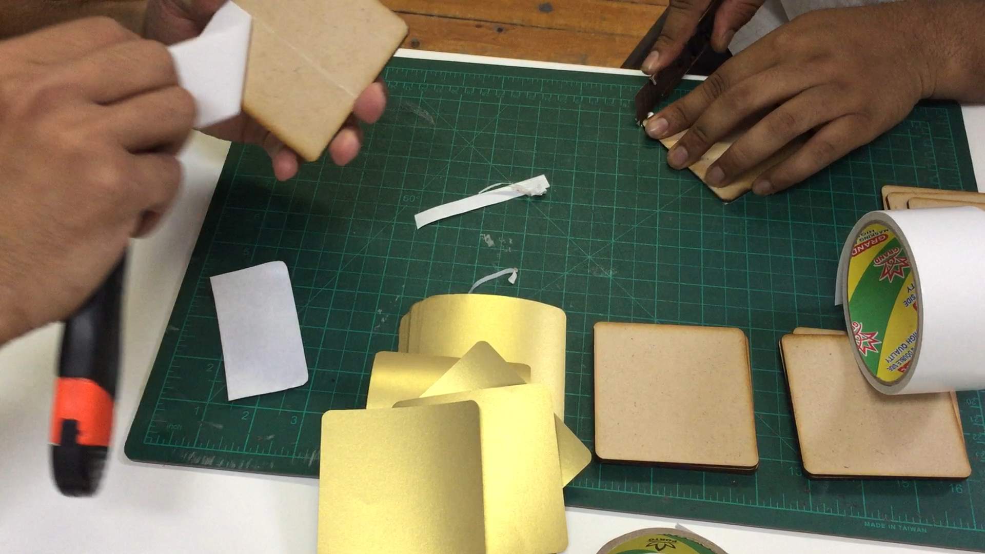
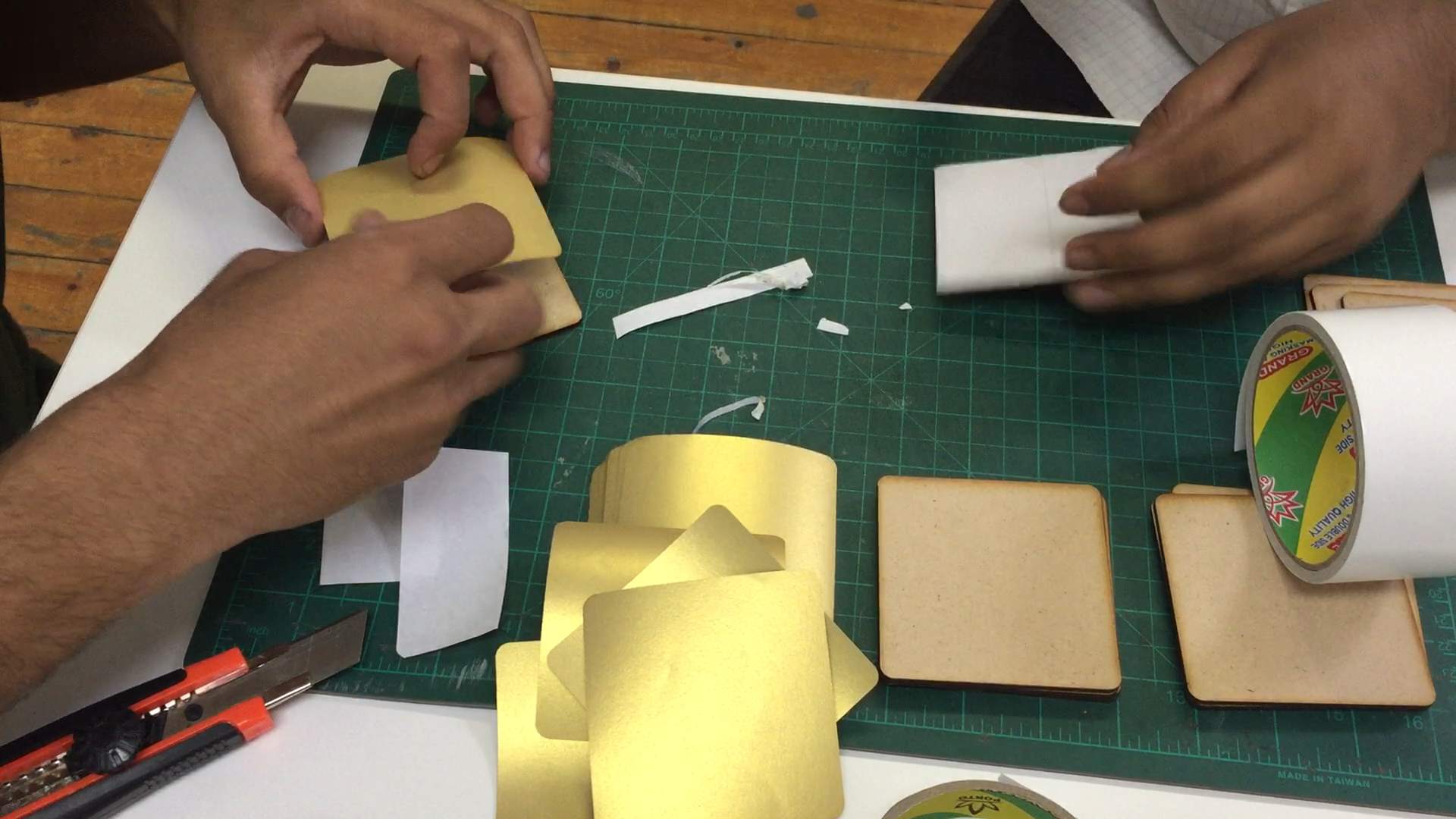
Then I brought a type of paper called crystal paper that gives a sort of a reflection of light when I it's subjected to light. so I cut it also by the laser cutter and sticked them to the plates I cut by a double-faced adhesive tape.
Embedded Programming
In programming the boards I had to make 2 codes, one for the master and another for the slaves, and I also had to change the address for each slave I will be programming. So I started with the master as following:
Master code
And what the master code smply does is that it includes the Wire.h library which is responsible for the I2C communication, and then the VL53L0X.h library which is responsible for the time of flight sensor. After that I only get the readings from the sensor which I put in a varable called distance and find out if the distance is in the range of from 0 mm to 300 mm then it will make a group of signals to each slave defined giving them 1 and 0 according to their position I made in the board.
#include <Wire.h>
#include <VL53L0X.h>
VL53L0X sensor;
void setup() {
  Wire.begin();                                         // join i2c bus (address optional for master)
  pinMode(3, INPUT_PULLUP);                             // set push button pin as input
  pinMode(8, OUTPUT);                                   // set LED pin as output ~Master board
  digitalWrite(0, LOW);                                 // switch off LED pin ~Master board
  sensor.init();
  sensor.setTimeout(500);
  sensor.startContinuous();
}
byte x = 0;
void loop() {
  int distance = sensor.readRangeContinuousMillimeters();
  if (distance > 0 && distance < 300) {                // Range 0-300
                                                       // slave 8
    Wire.beginTransmission(8);                         // transmit to device #8
    digitalWrite(8, !x);                               // turn off the LED on Master board
    x = 1;
    Wire.write(x);                                     // sends one byte "1"
    Wire.endTransmission(8);                           // stop transmitting
                                                       // slave 9
    Wire.beginTransmission(9);                         // transmit to device #9
    digitalWrite(8, !x);                               // turn off the LED on Master board
    x = 0;
    Wire.write(x);                                     // sends one byte "0"
    Wire.endTransmission(9);                           // stop transmitting
                                                       // slave 10
    Wire.beginTransmission(10);                        // transmit to device #10
    digitalWrite(8, !x);                               // turn off the LED on Master board
    x = 1;
    Wire.write(x);                                     // sends one byte "1"
    Wire.endTransmission(10);                          // stop transmitting
                                                       // slave 11
    Wire.beginTransmission(11);                        // transmit to device #11
    digitalWrite(8, !x);                               // turn off the LED on Master board
    x = 0;
    Wire.write(x);                                     // sends one byte "0"
    Wire.endTransmission(11);                          // stop transmitting
                                                       // slave 12
    Wire.beginTransmission(12);                        // transmit to device #12
    digitalWrite(8, !x);                               // turn off the LED on Master board
    x = 0;
    Wire.write(x);                                     // sends one byte "0"
    Wire.endTransmission(12);                          // stop transmitting
                                                       // slave 13
    Wire.beginTransmission(13);                        // transmit to device #13
    digitalWrite(8, !x);                               // turn off the LED on Master board
    x = 1;
    Wire.write(x);                                     // sends one byte "1"
    Wire.endTransmission(13);                          // stop transmitting
                                                       // slave 14
    Wire.beginTransmission(14);                        // transmit to device #14
    digitalWrite(8, !x);                               // turn off the LED on Master board
    x = 0;
    Wire.write(x);                                     // sends one byte "0"
    Wire.endTransmission(14);                          // stop transmitting
                                                       // slave 15
    Wire.beginTransmission(15);                        // transmit to device #15
    digitalWrite(8, !x);                               // turn off the LED on Master board
    x = 1;
    Wire.write(x);                                     // sends one byte "1"
    Wire.endTransmission(15);                          // stop transmitting
                                                       // slave 16
    Wire.beginTransmission(16);                        // transmit to device #16
    digitalWrite(8, !x);                               // turn off the LED on Master board
    x = 1;
    Wire.write(x);                                     // sends one byte "1"
    Wire.endTransmission(16);                          // stop transmitting
                                                       // slave 17
    Wire.beginTransmission(17);                        // transmit to device #17
    digitalWrite(8, !x);                               // turn off the LED on Master board
    x = 0;
    Wire.write(x);                                     // sends one byte "0"
    Wire.endTransmission(17);                          // stop transmitting
                                                       // slave 18
    Wire.beginTransmission(18);                        // transmit to device #18
    digitalWrite(8, !x);                               // turn off the LED on Master board
    x = 1;
    Wire.write(x);                                     // sends one byte "0"
    Wire.endTransmission(18);                          // stop transmitting
                                                       // slave 19
    Wire.beginTransmission(19);                        // transmit to device #8
    digitalWrite(8, !x);                               // turn off the LED on Master board
    x = 0;
    Wire.write(x);                                     // sends one byte "0"
    Wire.endTransmission(19);                          // stop transmitting
                                                       // slave 20
    Wire.beginTransmission(20);                        // transmit to device #20
    digitalWrite(8, !x);                               // turn off the LED on Master board
    x = 0;
    Wire.write(x);                                     // sends one byte "0"
    Wire.endTransmission(20);                          // stop transmitting
                                                       // slave 21
    Wire.beginTransmission(21);                        // transmit to device #21
    digitalWrite(8, !x);                               // turn off the LED on Master board
    x = 1;
    Wire.write(x);                                     // sends one byte "1"
    Wire.endTransmission(21);                          // stop transmitting
                                                       // slave 22
    Wire.beginTransmission(22);                        // transmit to device #22
    digitalWrite(8, !x);                               // turn off the LED on Master board
    x = 0;
    Wire.write(x);                                     // sends one byte "0"
    Wire.endTransmission(22);                          // stop transmitting
                                                       // slave 23
    Wire.beginTransmission(23);                        // transmit to device #23
    digitalWrite(8, !x);                               // turn off the LED on Master board
    x = 1;
    Wire.write(x);                                     // sends one byte "1"
    Wire.endTransmission(23);                          // stop transmitting
  }

  delay(500);
}
Now for the slave code I made the initiation for the I2C communication, then I made a function that operates every time it recieves any signals from the master and called it recieveEvent, but it needs to check if the limit switch is pressed or not first. But by having 2 limit switches I had to define one as 1 and the other as 0.
Slave code
#include <Wire.h>
#define LMT 9
bool y = true;
bool z = true;

void setup() {
  Wire.begin(11);                          // join i2c bus with address #11
  Wire.onReceive(receiveEvent);            // register event
  Serial.begin(9600);                      // start serial for output
  pinMode(8, OUTPUT);                      // set LED pin as output
  pinMode(10, OUTPUT);                     // set LED pin as output
  pinMode(0, OUTPUT);                      // set LED pin as output
  pinMode(LMT, INPUT_PULLUP);              // set LED pin as output

  digitalWrite(8, HIGH);                   // switch off LED pin
}

void loop() {
  delay(100);
}

                                          // function that executes whenever data is received from master
void receiveEvent(int howMany) {

  int x = Wire.read();                    // receive byte as an integer
  Serial.println(x);                      // print the integer

  if (digitalRead(LMT) == HIGH) {
    if (x == 1 && y == true) {            // if x equals 1 or HIGH
      digitalWrite(8, 1);                 // turn on LED 1 > means HIGH
      digitalWrite(10, 1);                // turn on motor clockwise 1 > means HIGH
      digitalWrite(0, 0);
      y = false;
      z = true;
    }
    if (x == 0 && z == true) {            // if x equals 0
      digitalWrite(8, 0);                 // turn off LED 0 > means LOW
      digitalWrite(10, 0);                // turn on motor anticlockwisw 0 > means LOW
      digitalWrite(0, 1);
      z = false;
      y = true;
    }
   }
  else {
    digitalWrite(8, 0);                   // turn off LED 0 > means LOW
    digitalWrite(10, 0);                  // turn off motor
    digitalWrite(0, 0);                   // turn off motor
    delay(20);
  }
}
Then I was working on making the logo for my project so I started by writing its name on AutoCAD software and removing some lines from the letters to make it stylish. Then I made a colored hatch inside the letters.
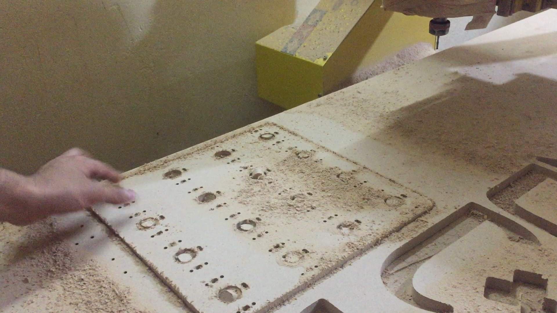
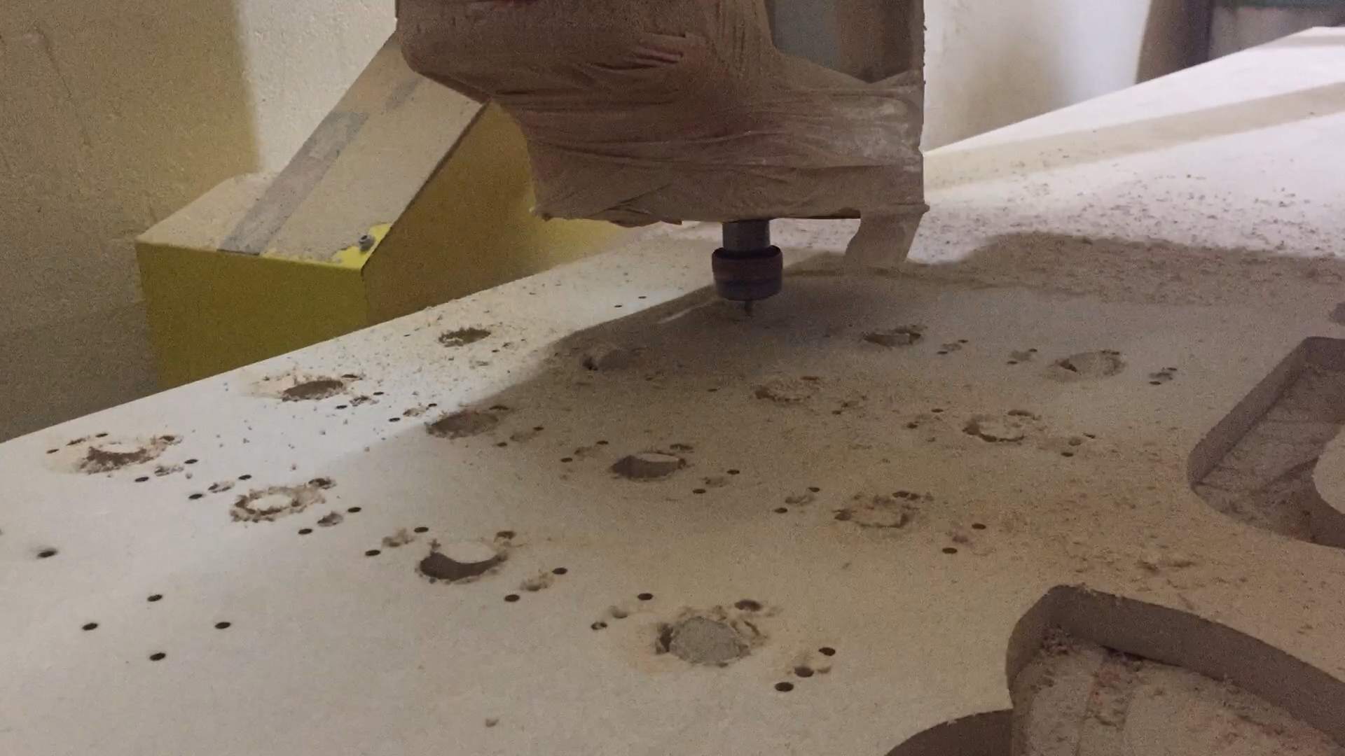
Computer-Controlled machining
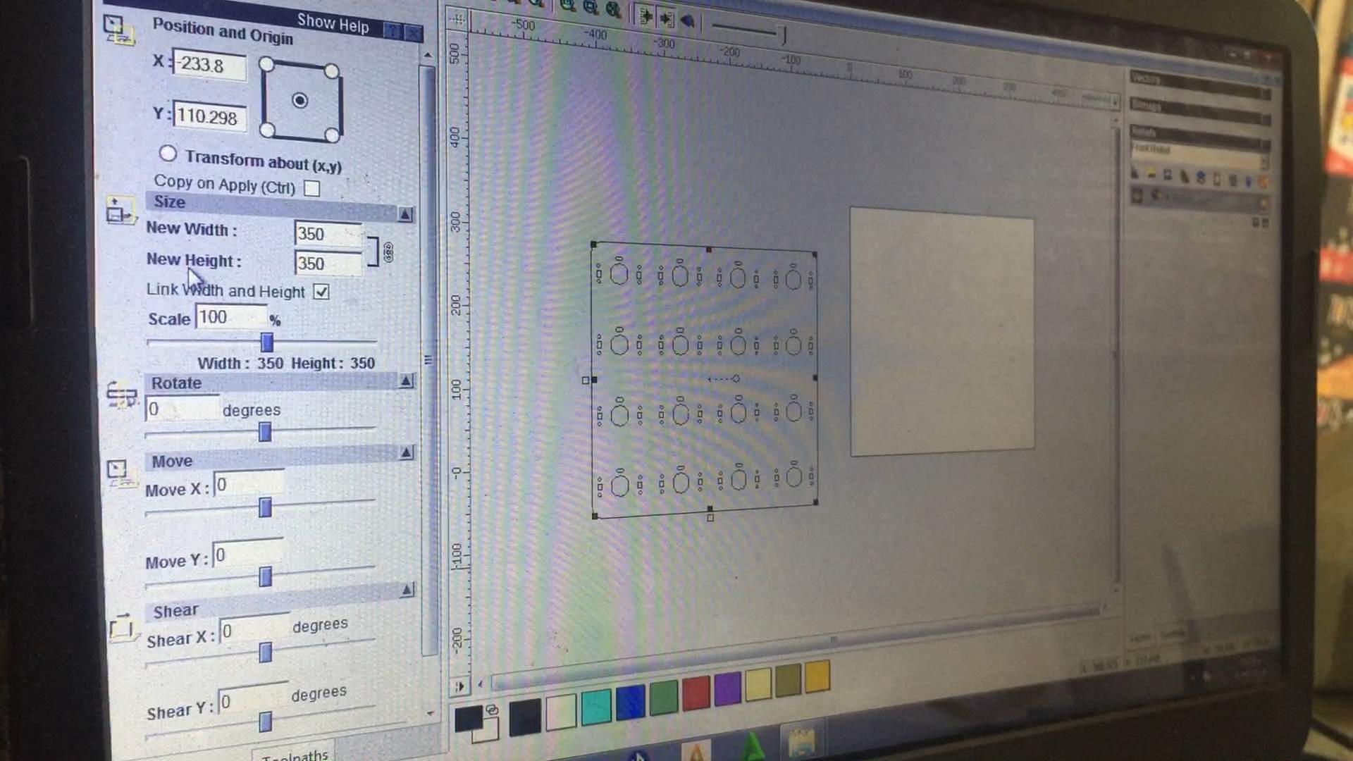
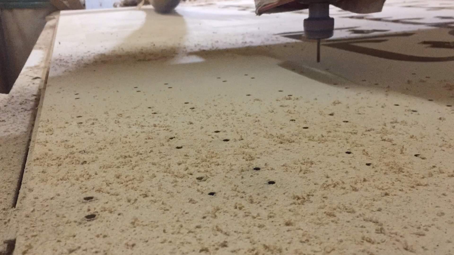
The board in the back that will be holding everything together had to be made on a thick wood sheet so I can't do that on a laser cutter and I had to do it on a router machine, so I made the design and exported the DXF file and cut that on an 18mm MDF wood sheet with a 4mm in diameter endmill. I made the toolpath and the g-code on Art-cam software.
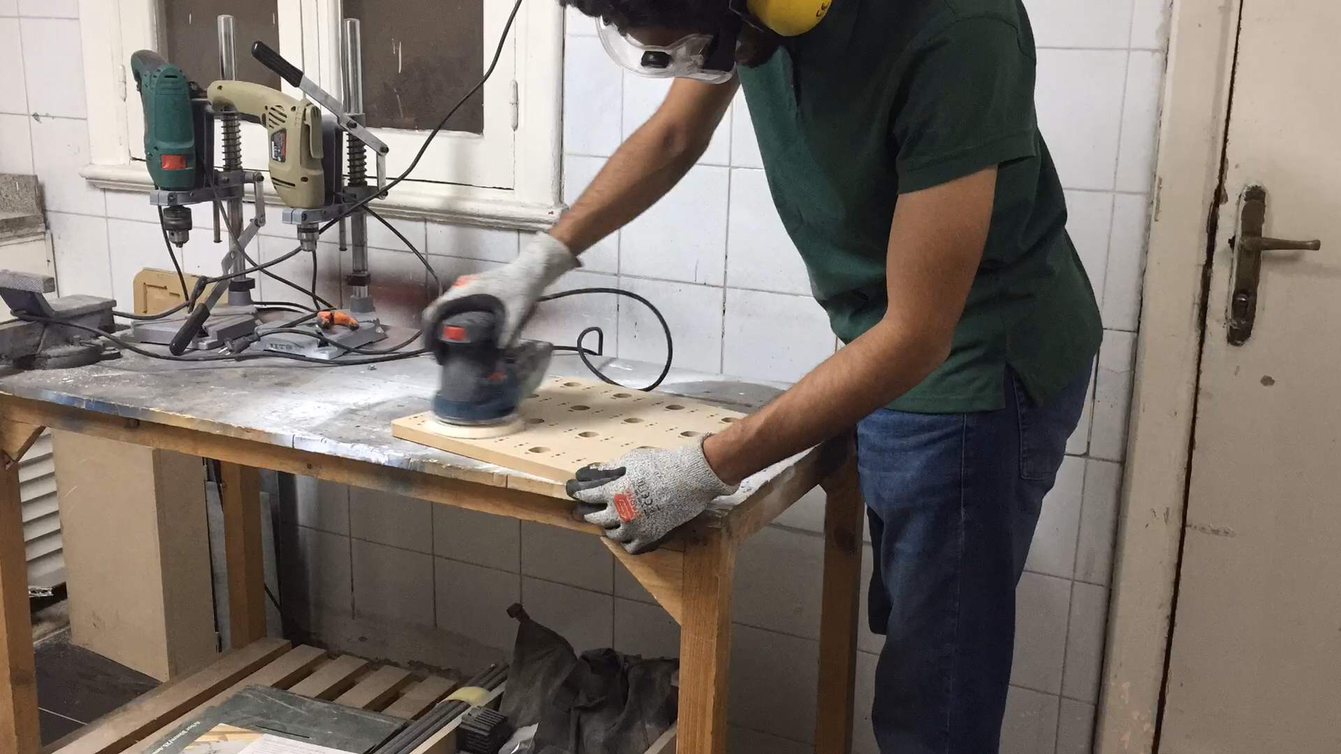
Then I wanted to sand it as it's surafce wasn't as good as needed so I used the circular sanding machine to sand it.
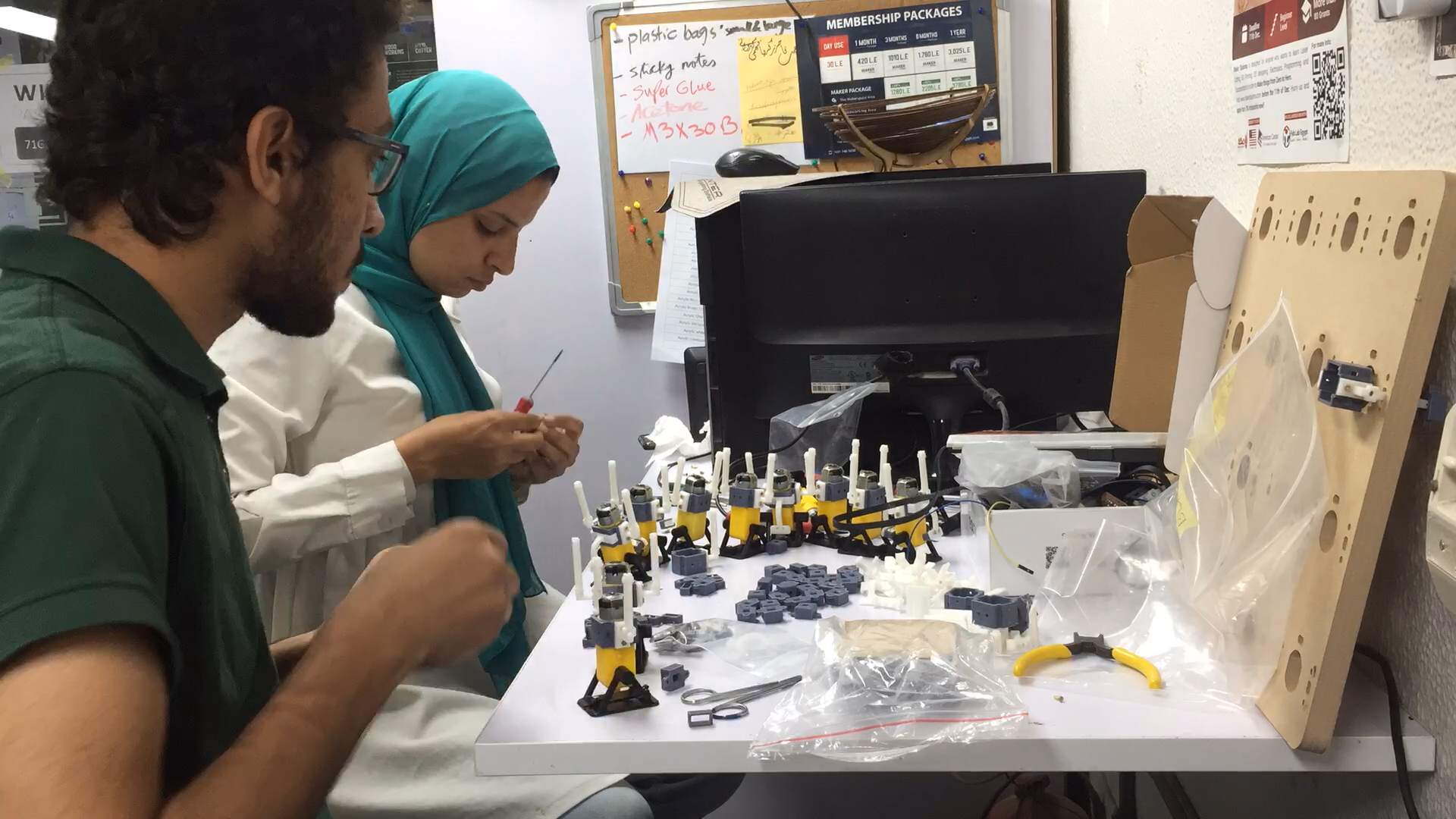
Assembling
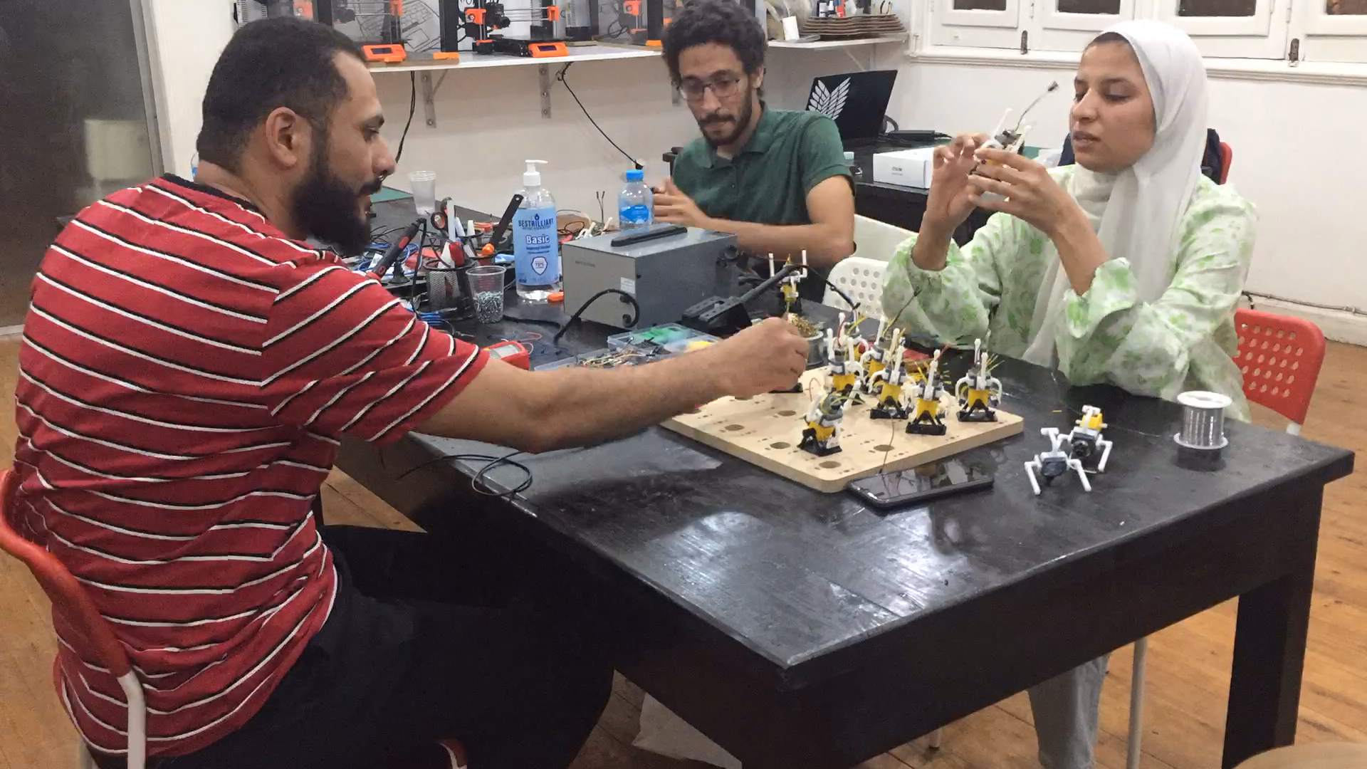
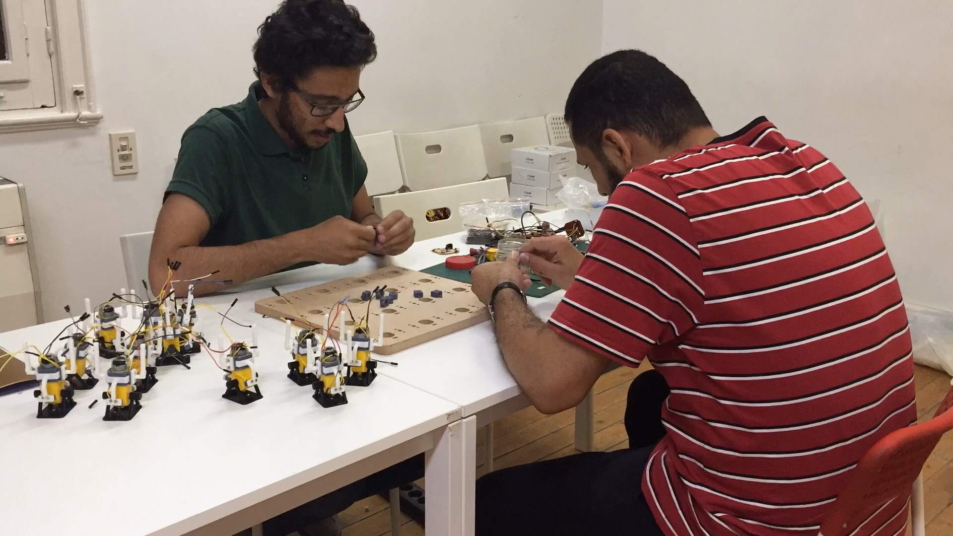
Now its time of assembling, actually it took us around 2 days to assemble the project and I had a lot of help from my collegues: Omar Seif, Amany Ayman, and Moiz Hatem. We assembed the moving mechanisms from the 3D printed parts, assembled the electronics, and all the systems together.
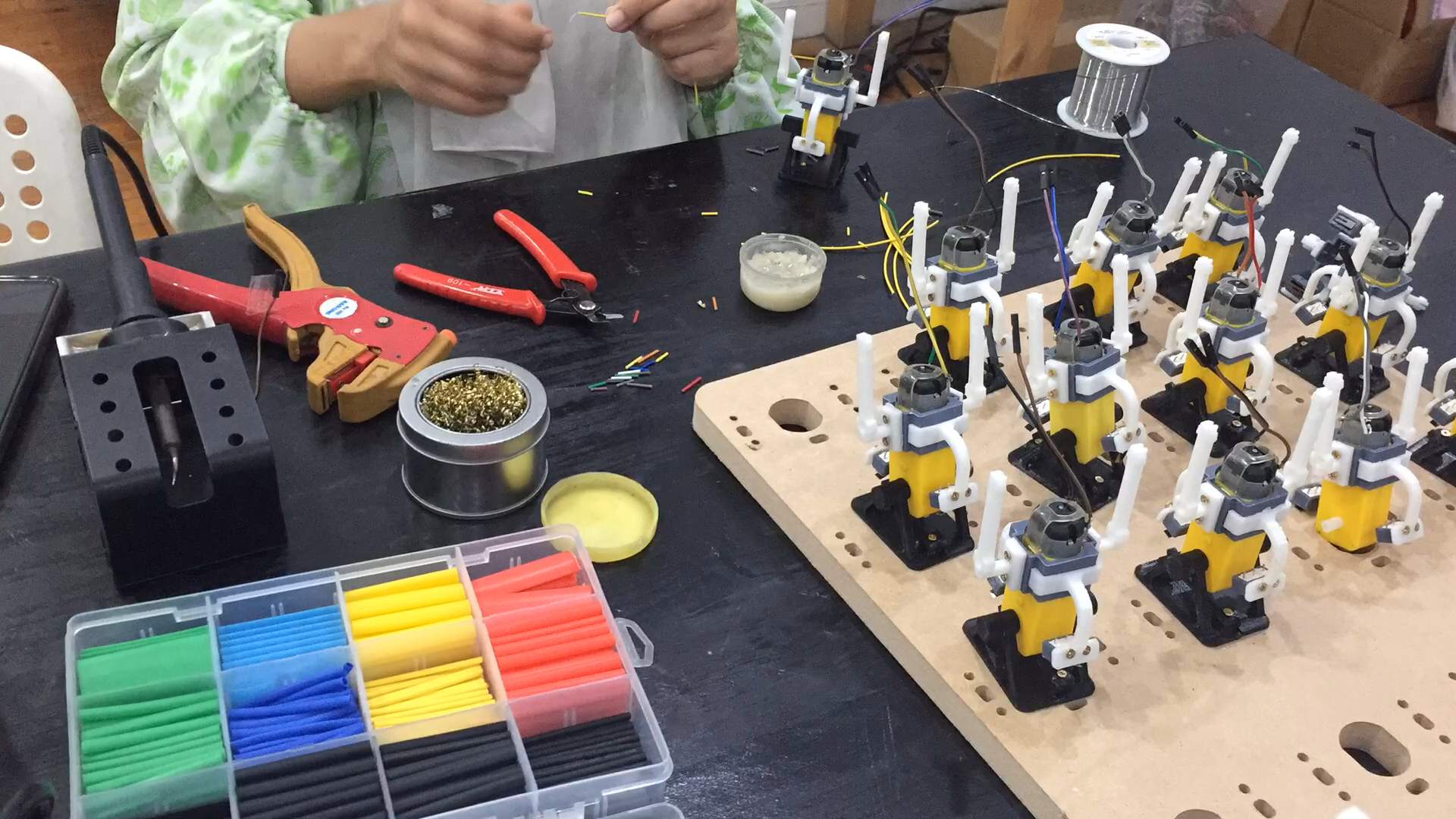
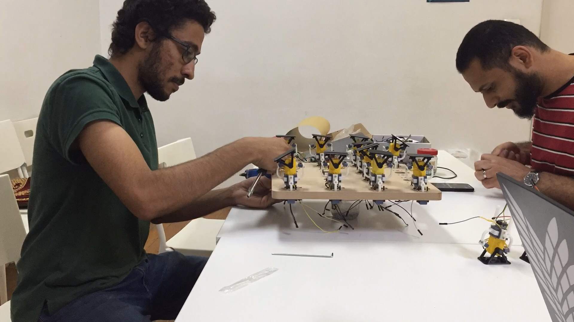
Testing
I had also the spirals idea in testing the systems in the project, as I managed to test every module alone and the connect it to the finished ones so I started by 1 module then 2 and so on, and till I had 4 modules working I saw that I didn't have that much time to complete testing and connecting so I stopped there.
1 module
2 modules
3 modules
4 modules
Then with the double-faced tape I sticket the plates to the module.
Sticking the plates
Testing after the plates
I wanted to make that project hanged on the wall.
And here you can see the full video I made for the presentation.
Acknowledgement
I want to thank here my parents who helped me alot in my project and through my whole Fab Academy journey, also my collegues Omar, Amany, and Moiz. My instructors Noha and Kamel and Saeed. And I want to thank Ahmed Ibrahim also for helping me alot in programming. Alot of thanks also for Mahmoud Abo El-Naga, Omar El-Safty Ibrahim AbdelGhany, and all Fab Lab Egypt's amazing team.